It is essential to master this subject, and in this article, we clearly present the concepts and applications of the electropneumatic system.
When it comes to industrial automation, for example, we can consider installing an actuator at this point, using a pneumatic system for its application.
This type of system is present in several companies, since it offers safety, compatibility with machine structures, low maintenance costs and high flexibility in installation (just connect a hose or pipe).
Pneumatics is an area of engineering that uses compressed air to create movement or perform mechanical work. Basically, air under pressure is used to operate cylinders, vibrators, valves, motors and other devices, facilitating automation in industries.
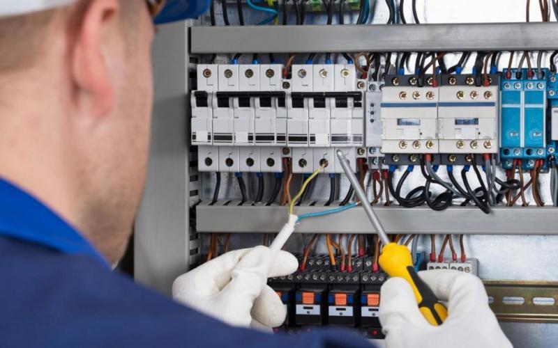
Electropneumatic systems combine electricity and pneumatics, two fundamental areas for industry. This combination provides efficient automation and precise control, making it essential to optimize operations and increase productivity.
The main components of a pneumatic system are:
- Air compressors: Generate compressed air for the entire system to work;
- Dryers: Remove all moisture in compressed air;
- Filters: Remove all residue from compressed air.
- “Lubrifil” Lubricators: Helps in the lubrication of all pneumatic actuators and valves.
- Valves: control air flow, direction and pressure;
- Pneumatic cylinders: Transform compressed air into movement;
- Pipes and fittings: Carry air from one place to another within the system.
The benefits of pneumatic systems include simplicity, speed, safety and low power consumption.
Electro-pneumatic systems stand out for their safety and versatility. The well-planned integration between electrical and pneumatic components ensures efficient separation between electrical controls and pneumatic devices, reducing risks in environments with explosive potential (classified areas), in addition to providing high-level automation.
Using the PLC (Programmable Logic Controller) allows you to control valves and other pneumatic components efficiently. By coupling position sensors, proximity sensors or even a linear ruler for precise analog control, this makes the system more flexible and capable of performing complex tasks, such as programming sequences of movements and proportional valve openings.
Symbology
The symbology of pneumatic valves plays a fundamental role in the operation of automated systems. In the industrial environment, the ISO 1219 and DIN 24300 standards are widely adopted to standardize these symbols, ensuring that anyone with knowledge of these guidelines can interpret pneumatic systems, regardless of their complexity.
These symbols are used to represent the components and their respective functions in pneumatic circuit diagrams, facilitating understanding and analysis by technicians, engineers and operators.
Pneumatic symbology provides detailed information about the operation and actuation of valves. The diagrams illustrate how the valves are actuated, the number of positions, the air flows involved and the number of connection ports available.
Valves
A pneumatic valve is a component designed to control the flow of compressed air in pneumatic systems. Its main function is to direct, interrupt or regulate the movement of air in the circuit, ensuring the efficient operation of pneumatic actuators.


What are paths and positions in Pneumatic Directional Valves?
Paths: is the number of connections available for use or direction of compressed air.
Positions: is the number of conditions that the valve can assume.
In the symbology, the number of positions is defined by the number of squares contained in the symbol.
Two squares, that is, two positions.

Three squares, that is, three positions.

The number of lanes is defined according to the application’s needs, and can be two, three, four or five, and are represented by the internal symbols that will be drawn inside the squares corresponding to the positions.
The symbols we find are arrows or Ts. The arrows indicate interconnection between lanes and the T indicates a closed lane. The arrows represent the interconnection of the lanes, but not necessarily the direction of flow.

The tracks are identified by letters or numbers, each manufacturer chooses whether the identification will be in accordance with ISO 1219, numbers or DIN 24300, letters, as per the table below:

Analog valves
Using the instrumentation of the devices, it is possible to configure variables continuously, such as pressure, flow, percentage of opening or closing of valves and cylinders. Analog valves allow fine adjustments, providing greater precision and flexibility in automated systems. They are generally actuated by analog signals, such as a voltage (e.g.: 0-10V), a current (e.g.: 4-20 mA) or a proportional pneumatic signal. They use a closed-loop control system to maintain the desired conditions with high precision.
A estrutura construtiva é diferente das convencionais, não admitindo uma pressão elevada de entrada, variação de pressão e/ou contaminação com água ou óleo.

Legal Notice
All information obtained on this website and related social media pages is for INFORMATIONAL purposes only. The Way Automation is NOT responsible for any damage or loss caused by the execution of actions related or not to the content described here. Always look for a qualified professional, follow the rules and use protective equipment for any work that involves electricity.

