There are different control signals present in industrial automation, which guarantee all communication, precision and reliability between controllers and actuators. In this post we will cover the main control signals used in industrial automation.
Digital Signal
Digital control signals within industrial automation enable countless logics and integration possibilities between devices, as they represent only two conditions: On/Off (button panels), True Bit 1/False Bit 0 (State Condition) and Present/Absent (sensors) . We commonly represent bits with a voltage level of 24Vdc as PnP/NpN digital inputs and outputs.
NOTE: Digital signal is a broad field of study, involving data processing, signal equalization, clocking and modulation.
PNP
Taking the negative 0Vdc as a reference, when activating the device a positive 24Vdc signal is sent.
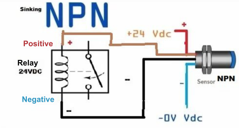
NPN
Taking the positive 24Vdc as a reference, when activating the device a negative 0Vdc signal is sent.
The PnP/NpN concept is used to drive various devices such as PLC, soft starter, inverter and drives in general.
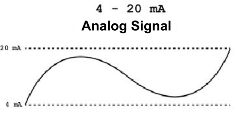
Analog control signals are dynamic information about the process, which varies as a function of time. Enabling the analog signal to measure and quantify quantities, such as temperature, level, speed and pressure and also control proportional valves, inverters and drives.
There are two main types of analog signals:
Voltage (0 to +10Vdc, -10 to 0Vdc or -10 to +10Vdc);
Current (0 to 20mA or 4 to 20mA).
Reference between sources
When working with two or more energy sources, it is necessary to pay attention to the reference (potential difference). Quick application example:
“Connecting a three-phase motor using PLC and frequency inverter” The PLC activates digital output “Q1” (PNP) and actuates the digital input “E1” (PNP) of the frequency inverter.
Inverters, PLCs, drives in general have their own sources, so the negative of both sources must be left in common so there will be a potential difference.
Legal Notice
All information obtained on this website and related social media pages is for INFORMATIONAL purposes only. The Way Automation is NOTresponsible for any damage or loss caused by the execution of actions related or not to the content described here. Always look for a qualified professional,follow the rules and use protective equipment for any work that involves electricity.